From kayak to foiling Moth
A three-month progression in Fusion 360, from my first complex surface model to a fully modelled foiling International Moth and a 3D-printed scale model.
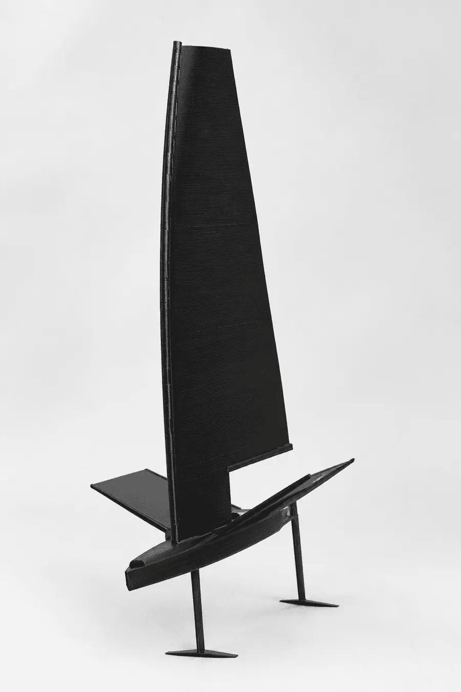
- 3Months, start to finish
- 7Systems modelled from scratch
- 1Printed scale model
- Fusion 360Modelling and rendering
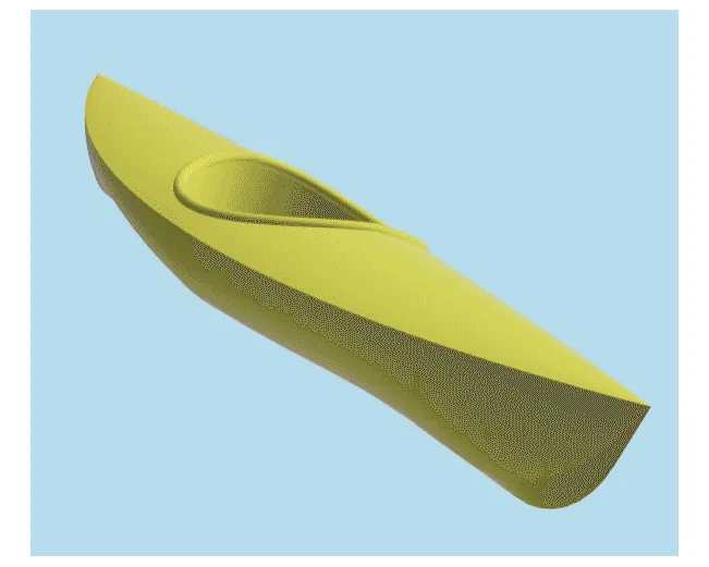
I started with a kayak
For my Professional Design Practice project, I wanted to push my Fusion 360 skills beyond the relatively simple CAD I was already comfortable with.
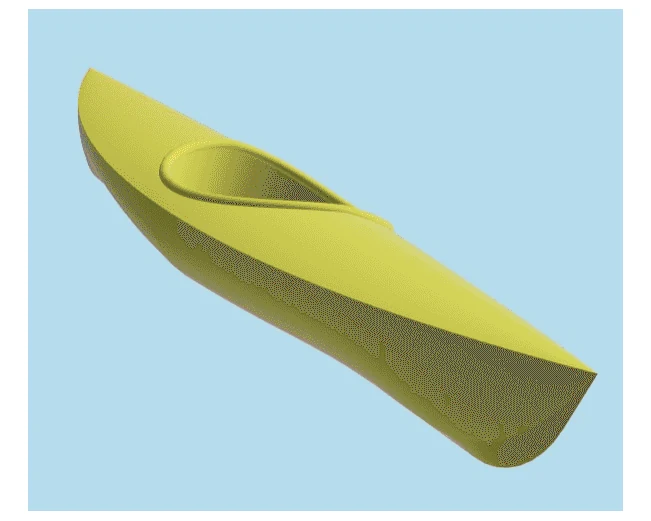
The kayak was my first step. It taught me how to work with complex surfaces, 3D sketches, lofts and sweeps, but it also taught me what not to do.
My biggest mistake was building the geometry without enough thought about how I might need to change it later. So when I started the Moth, I approached the hull completely differently.
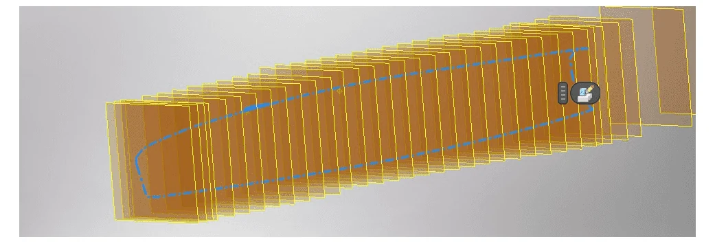
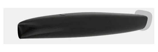
I built the model around a series of carefully positioned planes and parametrised sketches. Instead of trying to force the final shape together, I created a system that let me control the hull shape throughout the model.
It was much slower to set up. But once the structure was there, making changes became significantly easier.
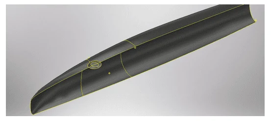
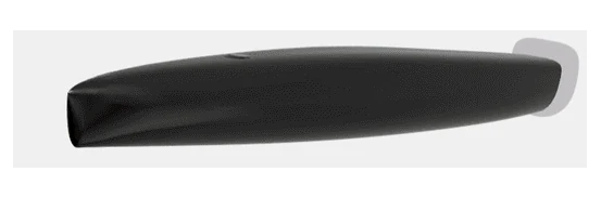
Good CAD isn’t just about making the geometry. It’s about building the model so that you can change the geometry.
The Moth hull became the most complex surface model I’d created, and the process completely changed how I approach CAD. Next step: turning the hull into an actual foiling boat.
How I modelled the foils and mechanisms
Once the hull was finished, the difficult part started. A Moth isn’t just a complicated shape. It’s a collection of aerodynamic surfaces and mechanical systems that all have to work together.
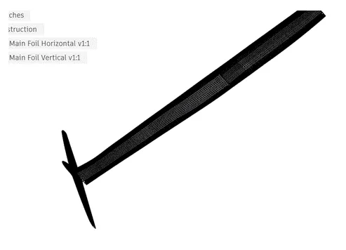
For the main foil, I started with established NACA profiles and lofted between sections to create the 3D geometry. This was a completely different approach to the hull: instead of designing the surface freely, the airfoil profile gave me a controlled starting point, and I could focus on how the profile changed along the foil.
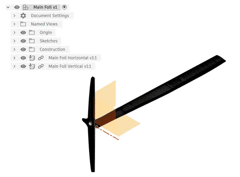
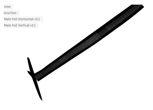
The rudder followed a similar process, but I created a new foil shape rather than simply scaling the main foil. Interestingly, it took significantly less time. That was a good sign that I wasn’t just learning Fusion commands, I was developing a repeatable modelling process.
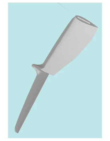
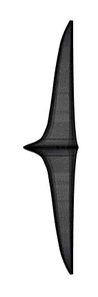
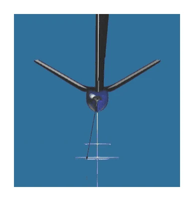
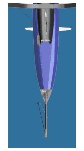
I then moved into the smaller mechanical systems. I modelled the wand, pushrod, lever components, prod, prod mount, foil connection and internal tube that make up the ride-height control system.
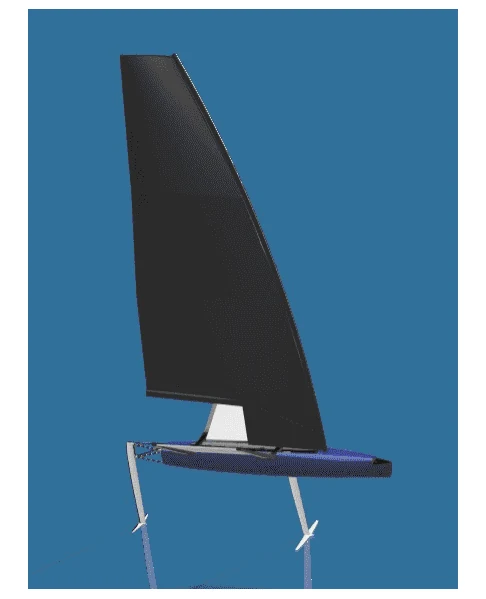
Does this look right?
How does this actually work?
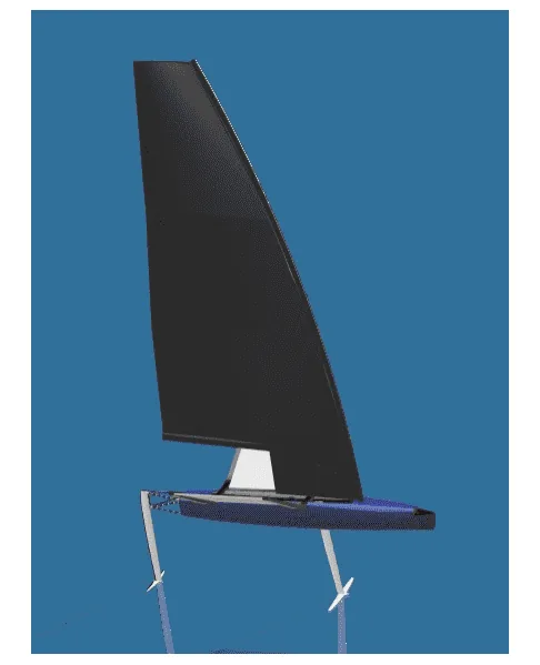
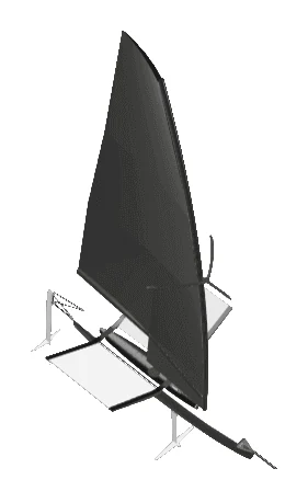
That shift from modelling appearance to modelling function is probably the biggest development I made throughout the project. The final CAD model contains the hull, sail, mast, foils, gantry, rudder and ride-height system, all built from scratch in Fusion 360.
Making CAD real
The CAD model looked great. Then I tried to 3D print it, and found out that looking correct in CAD doesn’t necessarily mean being manufacturable.
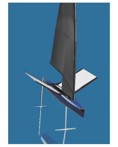
For the final stage, I wanted to turn the digital model into a physical scale model. The original had lots of small components and extremely thin aerodynamic surfaces. At full CAD scale they looked fine. At model scale, they didn’t.
So I redesigned the model specifically for the manufacturing process. I removed small components that wouldn’t add value at this scale, thickened the foils and sail, and went through multiple iterations to get the geometry printable.
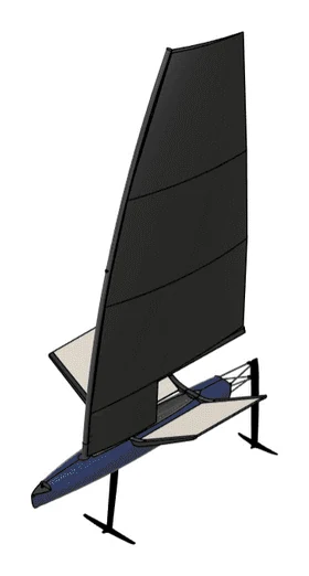
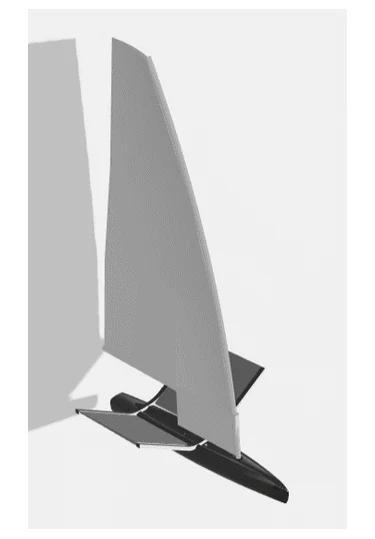
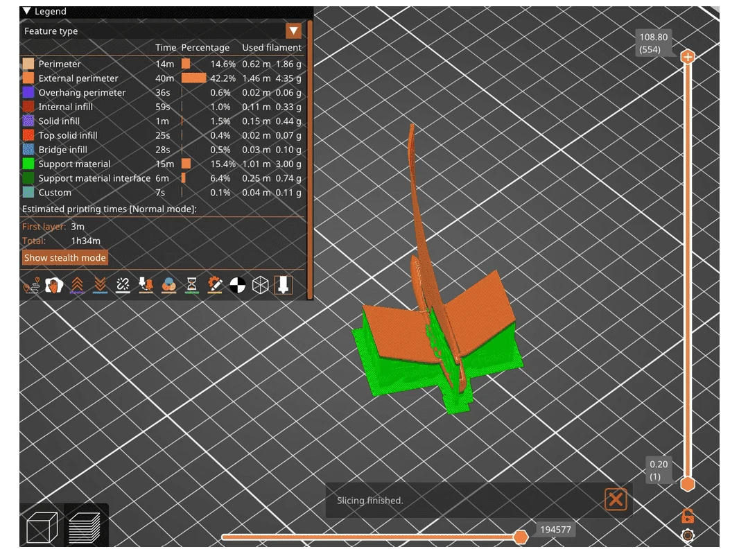
This was one of the most useful parts of the whole project, because the physical model exposed problems I hadn’t noticed on screen. Previously, I saw the CAD model as the finished product. Now I see it as a tool for developing the product.
- Model
- Identify problems
- Modify
- Print again
That feedback loop is something I want to take into future industrial design and engineering projects. The final step was rendering the completed Moth in Fusion 360 to communicate the design.
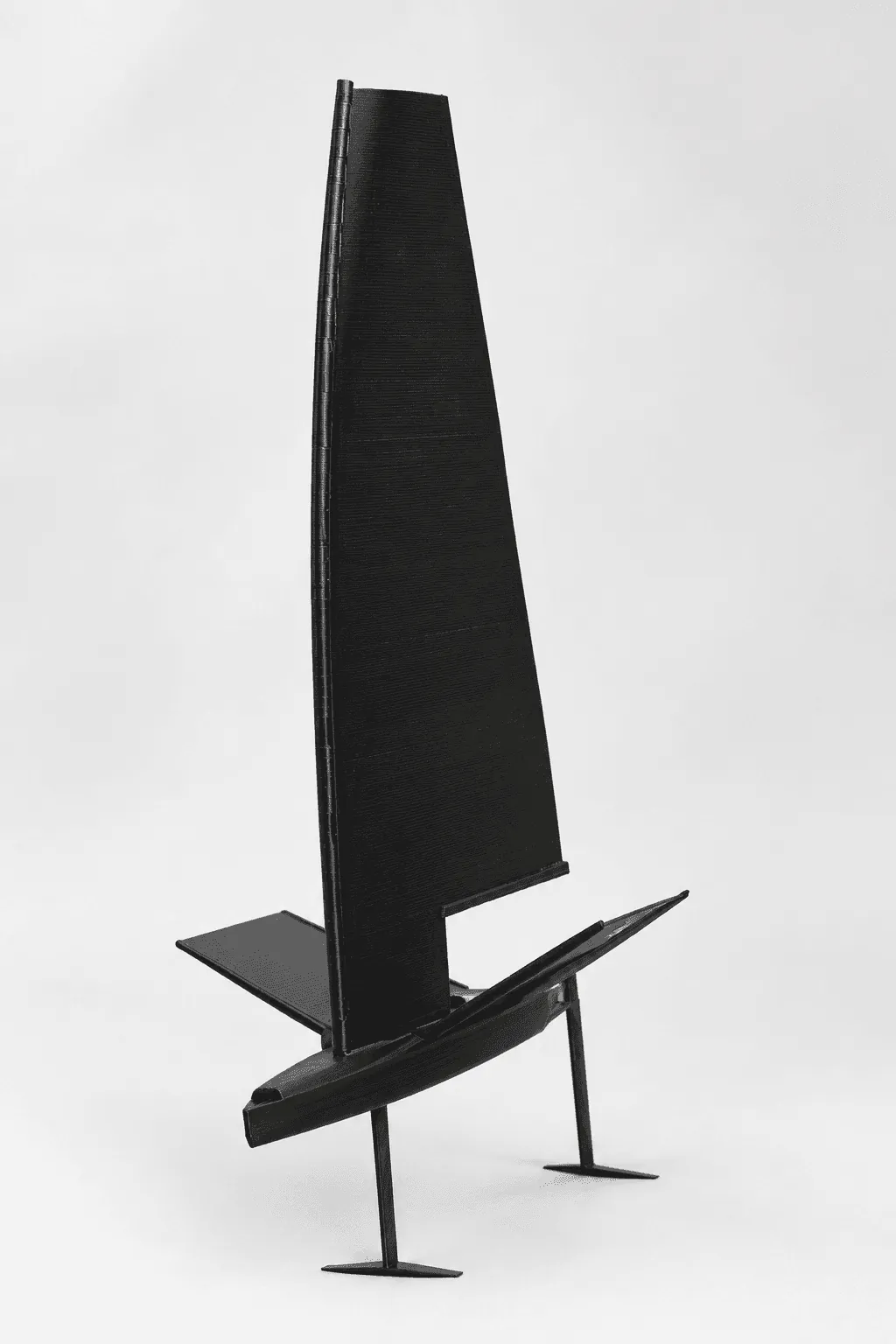
From a kayak to a fully modelled foiling Moth and a physical prototype, in three months of CAD.